2022: Volume 4, Issue 2
Past Issues
 Abstract
  PDF
PDFInvestigation of the Effect of Weathering of Selected Charnockite Rocks in Nigeria on Its Engineering Properties
Abdulraman SO1*, Musa VI2, Saliu MA2 and Abdulkadir IA3
1Department of Materials Science and Engineering, Kwara State University, Nigeria
2Department of Mining Engineering, Federal University of Technology, Nigeria
3Department of Geology and Mineral Sciences, University of Ilorin, Nigeria
*Corresponding author: Department of Materials Science and Engineering, Kwara State University, Malete, Kwara State, Nigeria, Tel: +2348033979980, E-mail: [email protected]
Received Date: April 23, 2022
Published Date: October 12, 2022
Citation: Abdulraman SO. (2022). Investigation of the Effect of Weathering of Selected Charnockite Rocks in Nigeria on Its Engineering Properties. Material Science. 4(2):15.
Copyrights: Abdulraman SO. © (2022).
ABSTRACT
The effect of alteration in the petrographic characteristics of charnockite on its strength, its engineering properties and transformations of the specific gravity which took place during weathering has been examined in this study. This study characterized selected samples of un-weathered and weathered charnockite rocks of Ijare, Ondo State, Nigeria. The physical properties determined were specific gravity, density, porosity, water content and water absorption while the mechanical properties investigated include the point load strength index. Results from the analysis carried out reveal: the point load index of 5.74Mpa and 3.72Mpa for unweathered and weathered samples; average uniaxial compressive strength of 136.90Mpa and 65.50Mpa for unweathered and weathered samples; slake durability of 98.80% and 97.80% for unweathered and weathered sample; Schmidt rebound value of 49Mpa and 45Mpa for both the unweathered and weathered samples respectively. The rock samples were also subjected to petrographical analysis whose result shows that weathering increases some investigated physical properties like porosity, water content and water absorption of the rock while decreasing the specific gravity and density. The result of the tests shows the bulk and dry densities increase for both the weathered and unweathered samples; increased degree of weathering equally results in a major reduction in the strength of the charnockite rock which is directly associated with changes in mineralogy and associated porosity. The point load strength, uniaxial compressive strength test and rebound hardness result values decreases because of weathering. Weathering processes also affected the physical properties of rock, mineralogy, chemical composition as well as the mechanical properties of the rock thereby reducing the strength and mechanical behavior of the rock materials.
Keywords: Charnockite, Ijare, Ondo State, Weathering, Petrographic, Mineralogical and Engineering Properties.
INTRODUCTION
Charnockite being one of the basement rocks in the earth’s outer surface reputable for esthetics has proven over time to be of a high economic value. Generally, un-weathered charnockite rocks have sufficient strength and are preferred for construction purposes as aggregates, concrete, railway ballast as well as dimension stones in the manufacturing of ornaments and tiles etc. Rock materials depends majorly on the relationship between the particles, inherent cementing materials and rock minerals for its properties especially the physical and mechanical ones. Therefore, the main minerals in charnockite are Quartz and Felspar (Orthoclase and Plagioclase) while some of the other minor ones are biotite, hornblende, pyroxene and microcline etc. In tropical region such as the Southwestern Nigeria, quartz has proved to be very stable that when charnockite is weathered, the quartz in it becomes sand grains. However, the orthoclase feldspar is not as stable. It yields potassium and carbonate ions, silica and flakes of kaolinite when orthoclase reacts with water and carbon dioxide.
Rocks affected by weathering suffers alteration in both its fabric and mineralogy as well as the strength properties. Although, results of several investigations conducted by previous researchers highlights the important role weathering plays in rock formation. Nonetheless, the immediate and resultant effect of weathering has great significance in determining the usage of rocks and its aggregates for both engineering works and design of geotechnical structures. The understanding of the changes of rock strength characteristics due to weathering is important for the discipline of Rock Engineering and Engineering Geology. [1] stated that both the mechanical properties of rocks and the value of strength are dependent on the inherent characteristics of the weathered rocks. The voids in rocks such as micro cracks also affect the rock’s physical and mechanical properties and also accounts for the anisotropy in most granites. Mineral composition, texture voids characteristics are the major factors controlling the physicochemical harm by most rocks introduced to new environments [2−4].
However, little or no research has been reported on how weathering affects or alter the physico-mechanical properties/characteristics of the charnockite rock in the Southwestern Nigeria. Hence, the key interest of this study is to assess the alteration of the petrographical, physical and mechanical properties of charnockite to further enhance a better understanding of its performances for various engineering applications. This research aims to know the role of weathering has in the engineering properties of selected charnockites in Ondo State. The objectives are to:
- ascertain the mineralogical composition of the selected rock types;
- highlight the engineering properties (compressive strength, porosity, PLI, hardness, slake durability, specific gravity, density and water adsorption of both unweathered and weathered rock materials; and
- evaluate the impact of weathering on the construction/engineering properties of charnockites.
It is our hope that this study will serve as a means of understanding the effect and the impact weathering has on the engineering properties of the selected charnockite rocks in Southwestern Nigeria as well as their uses in engineering works.
The area studied is ZIBO FM Quarry in Ijare, Ondo State which lies on latitudes 007° 20ʹ 25ʹʹN and 007° 20ʹ 26ʹʹN and longitude 005° 09ʹ 50ʹʹE and 005° 09ʹ 55ʹʹE (Figure 1). Lithologically, this outcrop is made up of migmatite, intruded by three petrological varieties of older granites. The migmatites consist of melanocratic paleosomes as well as felsic neosomes. The three petrographic varieties of older granite rocks recognized in this group are coarse-porphyritic biotite-hornblende, coarse-medium grained biotite hornblende, and medium-coarse grained charnockite.
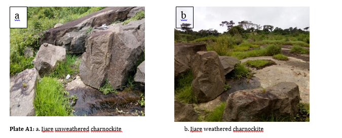
Figure 1: Geological Map of Ondo State, Southwestern Nigeria [5].
METHODS OF INVESTIGATION
2.1 Sample Collection and Preparation
This research was conducted through field work and laboratory analyses of samples collected from the charnockite outcrops’ location in Ijare area of Ondo State. GPS machine was employed in locating the study area. Block sizes of weathered and unweathered samples were taken from the outcrops. Samples were prepared (cut and ground) using the acceptable ISRM standard to get the physiomechanical properties of the rock [6]. The quantitative analysis of thin sections was done to the petrographic characteristics using Standard Polarizing Microscope and Scanning Electron Microscope for the analysis of the opaque minerals.
2.2 Rock Classification
Rock mass classification/characterization systems can be of considerable use in the initial stage of a project when little or no detail information is available. Colour being a significant noticeable feature of a rock has arguable being one of the most difficult tool to use for rock’s description. However, in hand specimen, there is a very distinct colour difference between the unweathered and weathered samples. The method adopted for the identification of the samples is the colour indicated by the grinded samples after milling.
2.3 Petrographic Examination of the Rock Samples
2.3.1 Procedure for preparing thin sections of rock samples
Samples from various locations were labelled according to their locations and the chips were cut from each of the samples. The obtained chips were trimmed to obtain smooth edges and grinded to obtain smooth surface with the aid of grinding machine. The grinded chips were then lapped on the successive grade of abrasive 400, 600 and 700. The material chip was placed on hot plate covered with Aluminum foil. The chip and the glass slide were allowed to warm up gently on the hot plate, after few minutes, the mounting medium was applied. The chip was mounted on the glass slide by placing it on chip. It was then placed on the slide bench to cool and set for about 24 hours. The chips were further grinded to reduce the thickness to about 90 microns. Lapping was carried out on grades of abrasives 400, 600 and 700. A paste of the first grade of carborandum 400 was made on the mixture from 400-600 and finally on 700, watching changes in colour from one grade to another under a polarizing microscope. A mineral that is quartz was picked as an index mineral, whose colour changed from purple on carborandum 400, to blue or deep yellow on caborandum 600 and finally to grey on caborandum 700. A standard thin section of about 30 microns was obtained. Razor blade was used to further trim the slide to sharpen the edges of the slides. This was done by carefully scrapping the excess aradite from the slide. The completed thin section was lightly heated on the hot plate with drops of canadal balsams. The cover slip was carefully placed over the slides and pressed down to exclude air bubbles. The slides were allowed to cool and then covered. After covering, the thin sections methylated spirit cotton wool was used to wash them. They were washed with detergent and rinsed with water until they were clean. The slides were air-dried. After drying, the slides were labelled with masking tape and stored in slide boxes.
2.3.2 Study of the Thin Sections
All the slides prepared from rock samples as thin sections were studied using the polarizing microscope while the mineralogical composition of the samples was determined using the modal analysis technique. Three different counts of all different spots on a slide were taken and all the counts were added together for percentage calculation of each mineral based on the total number of all minerals present.
2.4 Rock Density Determination
The essence of this test was to determine the dry and bulk densities of samples (irregular form). The dry density is the density of the rock in dried state (i.e. after oven dried) as density varies with moisture content. The apparatus used for the tests are:
- oven
- desiccator
- balance using 0.01g accuracy and a 100g range
- container for the sample with air-tight lid.
Irregular form of five specimens were prepared from the representative rock sample. The sizes of the specimen were prepared using the required procedure The Msub and Msat of the sample were measured to determine the volume of irregular samples.
.PNG)
The specimen was in a container, but without a cover, and dried in an oven to constant mass (for about 24 hours) at a temperature of about 105°C. After covering it, the specimen was allowed to cool in a desiccator for about 30 minutes. The mass (C) of the container (and cover) with the specimen was determined with an accuracy of 0.1g. The container with the cover was cleaned and dried and its mass (A) determined. This procedure followed acceptable ISRM standard using equations 2.1 to 2.4 [6].
2.5 Determination of Specific Gravity of Rock Samples
Specific gravity is the ratio of the weight in air of a given volume of a material at a particular temperature to the weight of the same volume of water at a particular temperature. The test was done using the ASTM (American Society of Testing and Monitoring) standard and procedure. ASTM D854-00 – Standard Test for Specific Gravity (GS) of Soil Solids by Water Pycnometer is calculated using the equation 2.5 below:
.PNG)
M1 = Mass of density bottle (pycnometer) + stopper.
M2 = Mass of density bottle (pycnometer) + stopper + sample.
M3 = Mass of water + sample + density bottle (pycnometer) + stopper.
M4 = Mass of water + stopper + density bottle (pycnometer).
2.6 Determining the Water Content of Rock Material
The determination of the water content of the rock material collected from the field is the main objective of this test. To get accurate result of the in-situ water content, the precautions of sampling, handling, transportation and storage should be followed to ensure that the water content is within the (recommended) 1% of the in-situ value.
Equipment used are:
- oven (24 hours at 105°C +/- 5°C)
- desiccator
- balance with accuracy of 0.1g and range of 1000g
- sample container (non-corrodible) with airtight lid.
Each representative sample of at least 5 lumps was prepared, measuring at least 50g and the minimum lump dimension was at least ten (10) times the maximum grain size of the rock. The lumps were placed in the container, covered by the lid and the mass (B) was determined using accuracy of about 0.1g. The process was repeated but this time keeping the lumps in the container and leaving the lid opened, oven-dried at a constant mass (for about 24 hours) at a temperature of 105°C. Again, the lids were replaced, and the lumps cooled in a desiccator for 30 minutes. The container with the lumps has its mass (C) determined using the accuracy of 0.1g. Thereafter, the container with the lid was cleaned, dried and has its mass (A) determined. This test was done three (3) times and the calculation of average of the result followed. The minimum lump dimension was at least ten times the maximum grain size of the rock. The procedure followed acceptable ISRM standard [6] using the equation 2.6 below:
.PNG)
2.7 Water Absorption Determination (WA)
Water absorption is considered as one of the most significant parameters for determining the weathering of rocks in the laboratory. This property can be considered as one of the most suitable, among routine tests, to reveal the presence of microcracks connected with weathering increase. Moreover, the direct connection between water absorption and porosity also involves a strict dependence of compression resistance to the capacity of a rock to absorb water. The procedure involves drying the specimen (in the open container) in an oven using a constant mass (for 24 hours) and at about 105°C temperature. After closing the container and cooling it in a desiccator for about 30 minutes, the determination of the mass (C) of the dry sample with the container (and the lid) is done using an accuracy of 0.01g. Thereafter, the specimen was saturated using water immersion technique in a vacuum that was less than 800Pa in 24 hours. Eventually, the calculation of the water absorption as the percentage (%) of the dry mass was done using the equation below:
.PNG)
2.8 Determining the Porosity of the Rock Material
This test was done essentially to determine the porosity of the rock specimens of irregular form. Porosity is defined as the volume of the pores in a rock that is expressed as a percentage (%) of the total volume of the rock. The equipment used are:
- oven (24 hours at 105°C +/- 5°C)
- desiccator
- balance; with a range of about 200g and an accuracy of 0.01g
- sample container (non-corrodible) with air-tight lid
- vacuum chamber with pressure less than 800Pa
Irregular form of five specimens from a representative sample of the rocks were prepared. The sizes of the specimen were made with a mass of at least 50g of irregular form and the minimum specimen dimension was at least ten times the maximum grain size of the rock. The bulk volume (V) of the specimen was determined through the measurement of the saturated-submerged mass (Msub) and the saturated mass (Msat) of the samples for the dimension of the specimen. The specimen was saturated by water immersion in a vacuum of less than 800 Pa for One (1) hour with periodic agitation to remove trapped air.
The specimen was removed from the water and surface-dried using moisten cloth. Necessary precautions were taken including removing the surface water and ensuring that no fragments were lost. The specimen was located in a container to avoid the loss of the mass during subsequent sample handling. The mass of the specimen plus container (B) was determined with an accuracy of about 0.01g.
The specimen (in the open container) was dried in the oven at constant mass (for 24 hours) and temperature (of 105°C). After closing the container and cooling it in the desiccator for 30 minutes, the mass (C) of the dry sample with the container (and lid) was determined with an accuracy of 0.01g. The container with the lid was cleaned and dried with its mass determined using an accuracy of 0.01g.
The procedure followed acceptable standard [6] using the equation 2.8 to 2.9.
.PNG)
2.9 Determining the Point Load Index of Rock Materials
Point load test is a simple test and usually used for the estimation of rock strength. Equipment used for this test consists of a loading frame that can measure the force required to break the sample and a system for measuring the distance between the two plate contact points. The test’s apparatus is: two-point load platens; a rigid frame; a hydraulically activated ram (with pressure gauge); and a device for measuring the loading points’ distance. The procedures conform with acceptable ISRM standard [7]. The point load test ensures the determination of the uncorrected point load strength index (ls). It should be corrected to standard equivalent diameter (De) of 50mm.
.PNG)
But if there is a significant difference, the result is reported as uncorrected strength and it can be multiplied by the correction factor, F; to get the corrected strength [8].
.PNG)
F = (D/50)0.45 (2.15)
F = correction factor; D = diameter (mm)
2.10 Determining the Rock Material’s Uniaxial Compressive Strength
This test is usually carried out to determine the unconfined (or uniaxial) compressive strength (UCS) of rock specimens of cylindrical form. It is mostly used for strength classification and the characterization of rocks that are intact. The UCS is adjudged to be the best in measuring the deformation, strength and the fracture characteristics of rocks. Like the above, its procedure is in line with acceptable ISRM standard [6].
Uniaxial compression tests on the unweathered and weathered (altered) charnockite was done on a MTS servo controlled hydraulic testing machine in accordance with ISRM guidelines [6]. In addition, axial and lateral micro-measurement N2A series electric resistance strain gauges were secured to each sample to record strain development on loading. The result of the axial and lateral strain was recorded on the PC attached to the machine in a Microsoft Excel text file. The volumetric strain was calculated from the ratio of axial strain to lateral strain. The following equation gives the strength of the rock according to ISRM standard [6]:
.PNG)
σc = unaxial compressive strength (UCS) of the rock (MPa);
Pmax = peak load (kN);
A = initial cross sectional area (m2)
2.11 Determination of Deformations in Unconfined Compression
The stress-strain curves are determined through this test. From the curve, the Tangent Modulus Et50, Modulus of elasticity, and the rock’s Poisson ratio were calculated. The apparatus used include a testing machine with sufficient capacity that is capable of applying axial load at a rate that conforms to the requirements. The steel platens with which the specimen was loaded consists of hardened steel and were more than double the diameter of the specimen. The upper bearing plate was uquipped with a spherical seat. And the centre of curvature of the spherical seat coincided with the centre of the top face of the specimen. During loading, the determination of the axial and lateral deformation of the specimen was done using dial guages. Meanwhile, the conversion of load measurement and axial deformation carried out during the different stages of the test to values of stress and strain was carried out with the formula below:
.PNG)
P = axial load (Newton); A0 = cross-sectional area of the specimen at the start of the test;
dL = the axial deformation of the specimen (m, and positive for a decrease of length);
L0 = the original length of the specimen.
As stated above, it is on the graph of stress versus strain that the compressive stress and axial strain are to be plotted. This is for the curve to give the best description of the behavior of the deformed rock especially from zero stress up to failure; in case the rock shows non-linear stress-strain behavior at low and high stress levels. Strain gauges attached to the rock sample during loading measures the axial and lateral deformation. The volumetric strain is calculated as follows:
.PNG)
εa = Axial strain; εr = Lateral strain
The Poisson ratio can be calculated from the formula below:
.PNG)
2.12 Determination of Slake Durability Index of Rock Materials
Rocks are said to be durable when they are resistant to breakdown under weathering conditions over time. When a rock with clay minerals mixes with water, the rock swells and slaking occur. To measure durability in rocks, the slake durability index (ID2) is used. It works by giving the proportionate information of the behaviour (mechanical) of the rock with respect to the amount of clay and some other minerals that are birthed as a result of the effect of weathering on them [9].
To carry out this test, samples containing 10 rock pieces were selected with each weighing between 40 to 60g; with the whole sample weight range of between 450 to 550g. This sample was then placed in a screen drum with both the sample and the drum oven-dried at a temperature of about 110°C (plus or minus 5°C) using a constant weight. After the sample has been allowed to cool to normal room temperature, the drum was coupled to a motor and rotated then immersed in distilled water at a speed of 20rpm for 10 minutes. The sample was again oven-dried at a temperature of 110°C ± 5°C using a constant weight. Thereafter, the sample was made to undergo a second wetting and drying cycle. It is after the second cycle that the slake durability index is calculated using the formula below:
.PNG)
ID2 = slake durability index (second cycle), (%);
B = mass of the drum plus oven-dried sample before the first cycle, (g)
WF = mass of the drum + oven-dried sample retained after the second cycle, (g)
C = mass of the drum, (g)
From the test, the visual and index classification was done in accordance with the appearance of the rock pieces remaining and the range of the ID2. The result is shown in Tables 2.1 and 2.2 below:
Table 1: Visual Description of the Rock Samples Retained in the Test Drum after the Second Cycle (after [10])
|
Type |
Description |
|
I |
Pieces remain virtually unchanged |
|
II |
Consists of large and small pieces |
|
III |
Exclusively small fragments |
Table 2: Slake Durability Index Classification (after [10])
|
ID2 (%) |
Durability Classification |
|
0-25 |
Very Low |
|
26-50 |
Low |
|
51-75 |
Medium |
|
76-90 |
High |
|
91-95 |
Very High |
|
96-100 |
Extremely High |
RESULTS AND DISCUSSION
3.1 Colour Characterization of Ijare Charnockite
Unweathered samples in the study area are massive, dark green in colour as a result of the feldspars in the charnockite. However, the colouration fades away with increased weathering of the charnockite. There is a slight discolouration of the weathered sample as shown in plates A1. From ISRM [6] and [11], the degree of weathering of volcanic rocks and granite is usually estimated from visual observations. Ijare weathered charnockite is classified to be slightly weathered from the visual observation of the rock sample which indicates discolouration and discontinuity surfaces and the unweathered sample is Grade I; with no visible sign of weathering or discolouration.
3.2 Petrographic Analysis Results
The result of mineralogical analysis of the unweathered and weathered charnockite shows the presence of quartz, hornblende, biotite, hypersthene and feldspar (plagioclase) as the primary minerals while the opaque minerals and zircon were the identified accessories. Quartz occurred as a minor mineral in both unweathered and weathered samples in the study area. The low quartz content affects the strength of the rock. The sample has high plagioclase feldspar than quartz. This observation conforms to the postulation [12]. Hornblende appears in brown colour, pleochroic; with dual cleavage directions. The secondary mineral in this setting was suspected to be hornblende. Hypersthene, on the other hand, has its colour ranging from neutral to light green when observed under plane polarized light but was pleochroic. The mineral has a high relief and one-directional cleavage. A brown – green biotite was seen in thin section; and also, pleochroic. It also has a higher relief, lath-like in form with a one-directional cleavage. Some of the flakes has inclusions of zircon. A further observation of the rocks’ thin section shows zircon and opaque minerals (likely iron oxide) as the accessories in the rock. Figure 2 and 3 shows the photomicrograph of the samples.
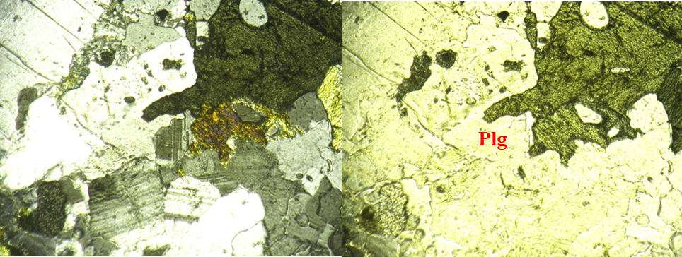
Figure 2: Photomicrograph of Ijare unweathered charnockite rock sample
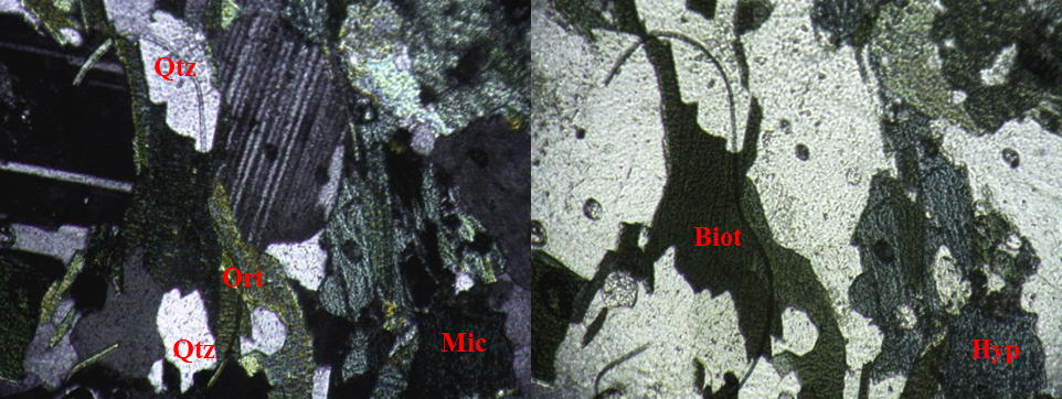
Figure 3: Photomicrograph of Ijare weathered charnockite rock sample
Table 3: Mineralogy of Ijare Charnockite under Transmitted Light Microscopy
|
Minerals |
Ijare Unweathered |
Ijare Weathered |
|
Composition (%) |
Composition (%) |
|
|
Quartz |
5 |
5 |
|
Microcline |
20 |
21 |
|
Orthoclase |
24 |
24 |
|
Plagioclase |
12 |
10 |
|
Opaque Minerals |
1 |
2 |
|
Olivine |
Not identified |
Not identified |
|
Hornblende |
15 |
12 |
|
Muscovite |
Not identified |
Not identified |
|
Pyroxene |
Not identified |
Not identified |
|
Hypersthene |
11 |
13 |
|
Biotite |
12 |
13 |
|
Total |
100 |
100 |
3.3 Properties (Physical and Mechanical) of Unweathered and Weathered Charnockite Rocks of Ijare
The result of laboratory analysis of physical properties of the charnockite rocks is shown in Table 3 above. Generally, for each physical index of unweathered and weathered samples, the value quoted is the mean of the tests carried out.
The mean bulk density of the weathered samples is 2.55g/cm3 while the mean bulk density for the unweathered samples is 2.60g/cm3 as shown in Figure 4. Similarly, the dry density of the samples from the studied area presented in Table 4 also revealed that the dry density for the weathered sample is 2.49g/cm3 while that of the unweathered is 2.59g/cm3 (Figure 1); indicating that the weathering has lowered the rock densities which is the main factor of strength for the rocks. Similarly, the specific gravity of the rock decreases with increasing degree of weathering. The specific gravity increases progressively from 2.48 in weathered sample to 2.61 for unweathered sample as shown in Figure 4.
The porosity for both weathered and unweathered samples is 0.82% and 0.79%. The porosity, natural water content and water absorption value increase progressively with increase in the degree of weathering in both samples. The higher percentage of water content and water absorption observed in the samples could be due to porosity increase of the weathered charnockite and the percentage composition of plagioclase and orthoclase which have affinity for water. The low porosity values obtained for the unweathered charnockite and high porosity values for the weathered samples indicated that with weathering the porosity of the charnockite has increased and hence reduces its strength because increase in porosity is an indication of low strength values. Also, the mean percentage water content values of the weathered and unweathered samples are 0.17% and 0.22%. The mean percentage water absorption of the weathered and unweathered samples are 1.90% and 1.63% respectively as shown in Figure 5. The increase in porosity water content and decrease in specific gravity and dry and bulk densities of unweathered and weathered sample agreed with [13 and 15] that; as the porosity increases, the dry and bulk densities decrease and vice versa.
Table 4: Summary result of Physical Properties of Ijare Charnockite
|
Rock Type |
Porosity, n (%) |
Specific Gravity (g/cm3) GY |
Dry Density, (g/cm3), P |
Bulk Density, ρB |
Natural Water Content, Wc (%) |
Water Absorption,Wa (%) |
Schmidt Rebound Value |
|
Ijare Unweathered |
0.79 |
2.61 |
2.59 |
2.60 |
0.17 |
1.63 |
49 |
|
Ijare Weathered |
0.82 |
2.48 |
2.49 |
2.55 |
0.22 |
1.90 |
45 |
.PNG)
Figure 4: Variation of bulk density, dry density and specific gravity with weathering Ijare Charnockite
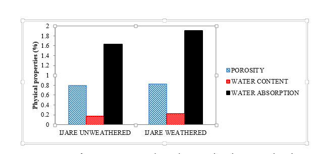
Figure 5: Variation of Porosity, Water Content and Water Absorption with Weathering in Ijare Charnockite
3.4 Mechanical Properties of Unweathered and Weathered Charnockite of Ijare
The mean of the point load strength index reduces as weathering increases in samples as expected because the weathering has reduced the quartz content of the weathered samples. The results for the point load strength index (PLI) values for the weathered charnockite is 3.7MPa while the PLI for the unweathered sample is 5.7MPa. From these results, it can be observed that unweathered samples though exhibit equigranular texture as compared with the weathered samples and has higher point load index values than the weathered samples. This can be attributed to the degree and extent of alteration in the weathered samples.
The uniaxial compressive strength has also been altered because of weathering. The average UCS value of unweathered samples is 148.04 Mpa which is because of the increase in bulk density, dry density and specific gravity, the unweathered charnockite samples also exhibit lower porosity, water absorption and water content. The weathered samples indicated a UCS value of 84.54 MPa. The weathered charnockite samples exhibited higher porosity in comparison to the unweathered samples. The higher porosity the weathered sample exhibited gave rise to the possibility of higher water absorption and water content. This exhibition of higher porosity which caused higher water content suggests the significant reduction in the strength of the weathered charnockite sample of the rock under study.
In the ISRM classification of Uniaxial Compressive Strength of Rocks [6], the unweathered sample is of a very strength which is between 100MPa – 250MPa while the weathered sample is classified to be of high strength with UCS between 50 MPa and 100 MPa. The low strength of the charnockite is suggested to be because of the increase in water content and porosity of the rock. Table 5 below shows the PLI and UCS result on the weathered and unweathered charnockite of Ijare:
Table 5: PLI and UCS of Ijare Charnockite
|
Samples |
PLI (MPa) |
UCS (MPa) |
|
Ijare Unweathered |
5.74 |
148.04 |
|
Ijare Weathered |
3.72 |
84.54 |
From the Deere and Miller Chart, the equivalent UCS of the rock is obtained by tracing the measured Schmidt rebound value and the density. The equivalent UCS obtained for Ijare weathered and unweathered samples are 100 MPa and 130 MPa respectively. The strength of the rocks which is between 100 MPa and 130 MPa is classified to be extremely high relying on the postulations of [6] in classifying UCS of Rock; very strong following the classification of IAEG on UCS of Rock and high strength in line with Deere and Miller Classification.
.jpg)
Figure 6: Variation of point load with weathering in Ijare Charnockite
.jpg)
Figure 7: Variation of UCS with weathering in Ijare Charnockite
3.5 Stress-Strain Analysis in Unconfined Compression Test
The stress-strain curves in unconfined state are plotted and presented in Figures 8 and 9 below. From these results, it was observed that the elasticity modulus of the unweathered samples seems higher than the weathered samples. This agreed with the observation of [14] that: the higher the modulus of elasticity, the higher the UCS of the rock. The ultimate deformation, ℇf (strain at failure) is considerably high in the weathered charnockite rocks as a result of probably the ductile behaviour of the materials. In the stress-strain diagram below, the shape shows great differences in the pre and post peak compressive behaviours in the unweathered and weathered rocks apart from the high compressive strength values, the slope of the ascending branch of the stress-strain diagram below is high in the unweathered charnockite as against the weathered component. This is not the case for the deformation capacity until peak load as it is higher in the weathered charnockites. This goes to show that the weathered and unweathered charnockite shows fragile responses that are associated to steep and irregular softening branch. For weathered charnockite, the descending branch is known to be mostly continuous and even smooth.
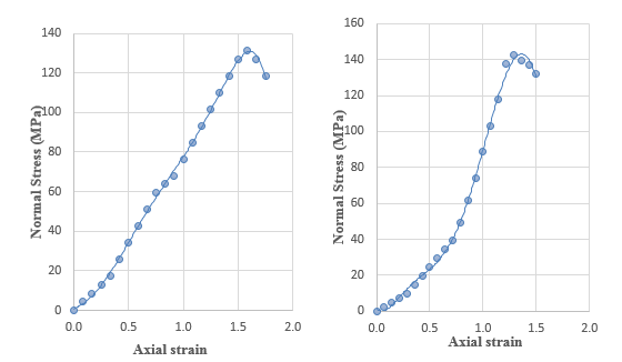
Figure 8: Stress-Strain Curve of Ijare Unweathered Charnockite
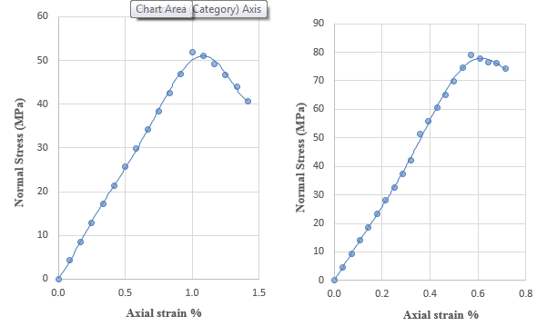
Figure 9: Stress-Strain Curve of Ijare Weathered Charnockite
3.6 The Slake Durability Index
Plot of Slake Durability Index (SDI) in the Figure 10 below reveals that the weathered charnockite of Ijare is 97.80% while the SDI for the unweathered component is 98.80%. This value is way higher compared to the extant standard for SDI classification for both the weathered and unweathered samples. The implication of this is that both the weathered and unweathered charnockite are highly durable and can be used for engineering purposes.
.jpg)
Figure 10: Variation of Slake Durability Index with Weathering
CONCLUSIONS AND RECOMMENDATIONS
4.1 Conclusions
The weathered and unweathered charnockite samples of Ijare have been investigated for its physico-mechanical properties, mineralogical composition, petrography and geochemical composition; in order to characterize the rock for engineering applications. Below are the conclusions made from the sample analysis carried out:
- the petrography of both the weathered and unweathered samples reveal that the increasing degree of weathering on the rock altered its mineralogy. There was a slight reduction in the quartz content of the weathered samples as against the unweathered samples. This reduction in quartz content suggests that slight weathering had occurred on the weathered samples. The variation in quartz content attest to the changes in the physio-mechanical properties of the charnockites.
- analysis conducted for the engineering properties of the unweathered and weathered samples suggests that the increase in specific gravity and bulk and dry densities of the unweathered samples of the charnockite contributed to the higher UCS, PLI and the SDI exhibited by these samples while the increased water content, porosity anf water absorption observed in the weathered samples compared to the unweathered samples contributed to the lower SDI, UCS and PLI exhibited by the weathered charnockites.
- relying on outcome of (b) above, the unweathered samples can be classified as unweathered due to the higher strength exhibited and also no visible sign of weathering or discoloration was observed in the physical inspection of the rock samples. The weathered samples can be classified as slightly weathered due to the lower strength exhibited, slight discoloration and reduction in the quartz content.
- result of this study shows that an evaluation of construction suitability can be accomplished. The Ijare charnockite is suitable and engineering worthy for construction purposes. It has good strength properties; low porosity and it is available.
4.2 Recommendations
1. Often times, rock aggregates and materials that were expected to have higher compressive strengths comes in low. It therefore could be that some of these materials might have contributed in a way to structural failures in some engineering construction works. In order to mitigate this, necessary engineering tests, statistical analysis and due diligence should be carried out on the rocks before they are applied as construction materials.
2. More researches should be carried out on other charnockitic outcrops as well as common rocks used for engineering constructions to determine their suitability for such purpose and the effects of weathering on them; before being put to use.
REFERENCES
- Gupta AS and Rao KS. (2000). Weathering Effects on the Strength and Deformation Behaviour of Crystalline Rocks Under Uniaxial Compression State. Journal of Engineering Geology. 56(3-4):257-274.
- Tugrul A. (2004). The Effect of Weathering on Pore Geometry and Compressive Strength of Selected Rock Types from Tyrkey. Journal of Engineering Geology. 75(3-4):215-227.
- Sousa LMO, Suarez del Rio LM, Calleja L, Ruiz de Argandona VG and Rey AR. (2005). Influence of Microfractures and Porosity on the Physico-mechanical Properties and Weathering of Ornamental Granites. Journal of Engineering Geology. 77(1-2):153–168.
- Ceryan S, Tudes S and Ceryan N. (2008). Influence of Weathering on the Engineering Properties of Harsit Granitic Rocks (NE Turkey). Bulletin of Engineering Geology and Environment. 67:97–104.
- Boeglin JL and Probst JL. (2001). Physical and Chemical Weathering Rates and CO2 Consumption in a Tropical Lateritic Environment: The Upper Nigeri Basin. Chem Geol. 148:137–156.
- International Society for Rock Mechanics (1981). Rock Characterization, Testing and Monitoring. In: Brown, ET. ISRM suggested methods. Commission on Testing Methods, International Society for Rock Mechanics (ISRM), Pergamon Press, Oxford, UK. 75-105.
- International Society for Rock Mechanics. (1985). Suggested Method for Determining Point Load Strength. Int. J. Rock Mechanics and Mining Science. Geomech Abstr. 22 (2):51-60.
- Lumb P. (1983). Engineering Properties of Unweathered and Decomposed Igneous Rock from Hong Kong. Engineering Geology. 9:81–94.
- Fookes PG, Dearman WR and Franklin JA. (1972). Some Engineering Aspects of Rock Weathering with Field Examples from Dartmoor and elsewhere. Q. J. Eng. Geol. 4:139– 185
- Franklin JA and Chandra A. (1972). The Slake Durability Test. Int. J. Rock Mechanics. Mining Science Geomach. 9:325 –341
- Hencher SR and Martin RP. (1982). The Description and Classification of Weathered Rocks in Hong Kong for Engineering Purposes. Proceedings of 7th South-East Asian Geotechnical Conference. 1:125–142.
- Ademeso OA. (2009). Deformation Traits in the Charnockitic Rocks of Akure Area, Southwestern Nigeria. Asian Journal of Earth Sciences. 2:113–120
- International Association of Engineering Geologists. (1981). Rock and Soil Description for Engineering Geological Mapping. Report by the IAEG Commission on Engineering Geological Mapping. Bull. Int. Assoc. Engineering Geologist. 24:109-114.
- Begonha A. and Sequira Braga MA. (2002). Weathering of the Oporto Granite: Geotechnical and Physical Properties. Catena. 49:57–76.
- Nicholson DT. (2001). Pore Properties as Indicator of Breakdown Mechanism in Experimentally Weathered Limestones. Journal of Earth Surface Processes and Landforms. 26:816-838.