2025: Volume 7, Issue 1
Past Issues
 Abstract
  PDF
PDFSynthesis and Characterization of Ag-Modified Composites as Counter Electrodes for Solar Cell Applications
Ramkumar Singh Dandolia1,*, Arvind Dandotia1, S.S. Tomar2, Radha Tomar3
1School of studies in Physics, Jiwaji University, Gwalior-474011, India
2Govt. S.L.P.P.G. College, Morar- Gwalior-474006, India
3School of studies in Chemistry, Jiwaji University, Gwalior-474011, India
*Corresponding author: Ramkumar Singh Dandolia, School of studies in Physics, Jiwaji University, Gwalior-474011, India, E-mail: [email protected]
Received Date: September 02, 2024
Publication Date: January 06, 2025
Citation: Dandolia RS, et al. (2025). Synthesis and Characterization of Ag-Modified Composites as Counter Electrodes for Solar Cell Applications. Material Science. 7(1):35.
Copyright: Dandolia RS, et al. © (2025).
ABSTRACT
Crystalline zeolite nanoparticles are successfully synthesized via the hydrothermal method and this zeolite was modified by using the ion exchange method. Polypyrrole/Zeolite nanocomposite was done by using polymerization techniques. The synthesized samples were characterized via different techniques like X-Ray Powder diffraction (XRD), Fourier Transformation Infra-Red Spectroscopy (FTIR), and Scanning electron microscopy (SEM) with EDAX, The XRD pattern confirms the hexagonal phase of the synthesized zeolite material. The composite material is crystalline in nature, with an average crystallite size of 35 nm. The SEM micrograph displays a regular hexagonal rod shape. Although, a dramatic shift is observed in the band gap of the samples is usually reduced up to 1.74 eV from 2.58 eV. The concentrations of the binder added to the composite pastes were varied to investigate their effect on the physical properties of the counter electrode and the electronic properties of the constructed DSSC.
Keywords: Zeolite, Nanoparticle, Synthesis, Photocatalysis, Spectroscopy.
INTRODUCTION
From the last few centuries, the field of Zeolite opens a new ray for researchers in order to explore the scientific community and engineering technology. Zeolites are one of the most commonly used solid catalysts in the material science and chemical industry because of their unique microporous frameworks and shape selectivity [1,2]. Several zeolites are used for the performance of catalysis but the Zeolite-Linde Type L (LTL) is better option for photocatalysis. Earlier reports investigated that Zeolite-Linde Type L have 1D-12 membered ring channels [3,4]. In addition to that these zeolites possess some important properties which shows the requirement for better scientific advancement. The Zeolite-Linde Typr L shows best properties especially for the longer chains, due to the diffusion limitation of one-dimensionally linear channels [5,6]. During the past few years, synthesis and catalytic applications of nano-sized zeolites with shorter channels have been proven to be an effective strategy for enhancing the performance in a variety of diffusion-limited hydrocarbon conversions [7,8]. Due to waste consumption and contamination, the growth of industries poses a serious threat to the environment worldwide. More efforts should be made to reduce environment pollution. One effective method to address this significant issue is by photocatalysis [9]. Although numerous types of materials are employed for catalysis such as chalcogenides, metal oxides and perovskites [10,11]. Zeolites’ porous cage like structure finds numerous applications, including gas detection and cleaning [12,13]. Zeolites can be successfully synthesized by several methods, such as the salinization, confined space synthesis and microwave synthesis method [14,15]. Nano-sized Zeolite-Linde Type L prepared by microwave method had been reported. Due to the less stability of these metal oxides and perovskites, researchers have found that Zeolites are considered to be the prime candidate for photocatalysis because’ of high selectivity to C-8 aromatics in n-octane aromatization due to the lower extent of secondary hydrogenolysis [16]. However, the microwave synthesis method is considering as energy consuming and not suitable for industrial applications and technological catalysis [17]. Therefore, it is extremely desirable to develop a cost- effective and easy scale-up approach to prepare nano-sized Linde Type L Zeolites with improved catalytic performance. Fortunately, a few researchers have observed that the incorporation of a small quantity of barium could facilitate the formation of nano- sized Linde Typr L Zeolites [18]. To the best of our knowledge, the explanation for the effect of Ba on the Linde Type L crystallization process is still unclear. The comprehensive understanding of the formation process is also significant for more scientifically modulating Zeolite crystal sizes. In addition to that the systematic study for the effect of Linde Type L crystal sizes on the n-alkane aromatization needs to be further addressed. Non- acidic Linde Type L Zeolite of one-dimensional 12-membered ring channels of 0.71 nm with platinum loading exhibits the exceptional performance of alkane aromatization as first reported by Bernard et al. Nano-sized Linde Type L Zeolite was successfully synthesized via the hydrothermal method [19,20]. Zeolite- Linde Type L has a hexagonal crystal structure (space group P-6/mmm) with unit cell constants a = b = 18.4 and c = 7.5 [21,22]. Zeolite - Linde Type L has attracted a lot of attention in the last 20 years because of its uses in catalytic processes, separations, and photonic devices [23]. For many years, iron catalysts supported on various materials have been frequently used in Fischer-Tropsch processes. By combining the benefits of iron and Linde Type L Zeolites, ultra-fine Fe- Linde Type L Zeolite nanocrystals may be synthesized, which could be useful in catalytic and ion exchange applications. In this work, nano-sized Linde Type L Zeolites were successfully synthesized via the hydrothermal method. The synthesized material was characterized by various techniques including X-ray diffraction (XRD), ultraviolet-visible (UV-Vis) spectroscopy, scanning electron microscope (SEM), Fourier transforms infrared spectrometer (FT- IR), more importantly, and the synthesis sample used the check performance of photovoltaic activities analysis.
Experimental Section
Reagents
Potassium Hydroxide, Silica Sol, Aluminium Hydroxide, Magnesium Nitrate, Copper Nitrate, and Pyrrole is purchased from Fisher Scientific, sigma, CDH Company, Merck, Fisher Scientific, Sigma. The entire chemical used in the synthesis is analytical grade and does not need further purification.
Synthesis of Zeolite- Linde Type L
The synthesis of Zeolite- Linde Type L has been carried out by taking 10.13 g Potassium Hydroxide, 5.27 g Aluminium Hydroxide is dissolved in 16.66 ml double distilled water and the reaction mixture is heated until a clear solution 'A' is obtained. Solution A is allowed to cool to room temperature. In a separate beaker 50.08 ml silica sol, 4.83 g magnesium nitrate solution was added to 33.0 ml of de-ionized water and mixed by stirring for about 3 minutes until a homogeneous solution 'B' is formed. Then the solution A and B are mixed to form a homogenous suspension and 8.33 ml of de-ionized water are added to it. The above suspension solution is stirred until thickening starts. The resulting gel is placed in a Teflon-lined autoclave and kept in an oven preheated to 175° C for 48 hours then after, the autoclave is removed from the oven and immersed in cool de-ionized water. The material inside the autoclave is centrifuged at 10,000 rpm and washed until its pH value reaches 9 and subsequently dried at 150°C in an oven for 16 h. The dried sample is crushed into a fine powder and calcined at 540°C for 7 hours.
Composite of Zeolite-LTL/PPy
1 gram of Zeolite-Linde Type L and 1 ml of Pyrrole are dispersed in 35 ml of de-ionized water and undergo sonication for 15 minutes. After sonication 0.72 Mole powder of FeCl3.6H2O is added to it and stirred it for 2 h. Finally, the composite is washed with double de-ionized water and dried at 50°C for 24 h in the oven.
Modified Zeolite to make a paste
To create a homogeneous paste with uniform composition, the required amount of Modified Zeolite powder was mixed with 15 ml of ethanol and stirred for 10 minutes; this solution is then placed in an ultra-sonicator for 15 minutes.
Fabrication of Devices cleaning of substrates
Fluorine-doped Tin Oxide (FTO) coated conducting glass substrates with a sheet resistance of 15Ω/cm2 were cut into small pieces measuring 1×1 cm2 by using a diamond cutter. The substrates were then ultrasonically cleaned for 10 minutes each with detergent, ethanol, acetone, and de-ionized water. These cleaned substrates are dried in a hot air oven set to 60°C for 10 minutes. This type of cleaning ensures the removal of all dirt including dust, fingerprints, oil contents, and other contamination materials that were left behind after manufacture. This improves transparency while also providing a good conduction path for electron collection. Substrates should never be handled with the bare hands.
Deposition of nanocomposite paste on the substrates
A single-layer mask is produced on the conducting side for the photoanode using adhesive tape (Magic tape-cello type). The Mask is designed with a 0.25 cm2 active. The required or desired amount of TiO2 paste was applied to one edge of the unmasked area and uniformly spread over the substrate using the doctor blade technique.
Heat treatment for photoanode
The deposited paste-based film was left out untouched for 15 minutes. All Tapes were carefully removed and the film calcined at 450°C for 30 minutes and cooled to 80°C. In this process, the film colour was brown at a higher temperature and turned to brownish-white when cooled down it. The calcination process was done to ensure the removal of all the solvents from the deposited layer on the film, leaving the tiny pores empty. It also promotes dye adsorption, which results in more excited electrons.
Dye sensitization of photoanode
The sensitization of a photoanode requires that the film be immersed in a dye solution for an extended period of time. Typically, this was accomplished by completely immersing photoanodes in the dye solution for 20-24 hours in a dark environment, after which the stray particles were washed off with ethanol to remove extra dye particles.
Preparation of the Counter Electrode
The CE preparation was done by cleaning FTO substrates as described in above section. Counter electrodes were prepared by a doctor blading technique, pasted of modified silver form Zeolite-polypyrrole paste onto the substrates, followed by calcination at 80 °C for 15 minutes.
Assembling the dye-sensitized solar cell
The working electrode and CE were sandwiched together before applying thermoplastic sealant and pressing firmly against the hot plate at 100°C for 1 minute. The structure of the Solar cell is shown in figure 1 and the flow chart for the fabrication of this process is shown in figure 2.
Filling of Electrolytes
The high-stability electrolyte solvent was filled between the working and CEs then sealant by a paper clip. The final structure of the fabricated DSSC was connected to the crocodile clip with the multi-meter and checked the conductivity.
Characterization
The structural property of synthesis material is determined by the XRD studies using Rigaku Mini-flex 600 diffractometer at operating 40 kV and 30 mA in the 2 [endif]--> Range 2° to 90° with
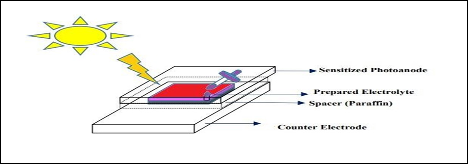
Figure 1. Fabrication of DSSC Solar cell.
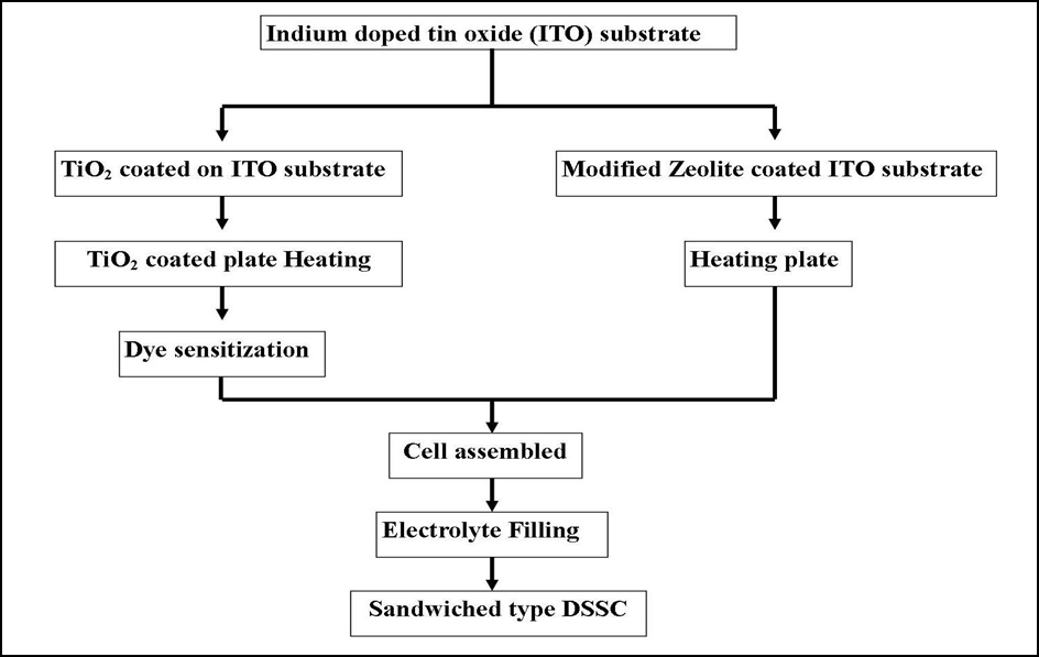
Figure 2. Flow chart of DSSC fabrication.
Cu Kα (0.15406 Å) radiation. The analyses of SEM and Energy Dispersive Spectroscopy (EDS) were used to perform morphological and compositional analysis using Philips Model-Quanta 200 FEG. The FT-IR spectrum is recorded using a PerkinElmer spectrometer ranging from 450 to 4000 cm-1.
RESULT AND DISCUSSION
XRD Analysis
The crystal structure, phase identification, crystallite size and presence of Zeolite Linde Type L (Zeolite-LTL), Polypyrrole (PPy) and Polypyrrole/Zeolite Linde Type L (PPy/Zeolite-LTL) nanoparticles samples were all analysed using Powder X-ray diffraction spectra. The diffraction peaks exemplify the presence of zeolite-Linde Type L and Polypyrrole thus verifying the formation of Polypyrrole/Zeolite-Linde Type L nanocomposites. The powder XRD patterns of zeolite-Linde Type L, Polypyrrole and Polypyrrole/Zeolite Linde Type L nanoparticles are shown in Figure 3. All three samples have indicating different structures and showing different characteristic peaks. XRD patterns of both Zeolite Linde Type L and Polypyrrole samples showed sharp and distinct reflections indicate that the samples are highly crystalline. In both samples (Zeolite- Linde Type L and Zeolite- Linde Type L/Polypyrrole), the reflections are indexed based on the hexagonal crystal system which is showing good agreement with the Linde Type L Zeolite structure [25]. The ion exchange in the Zeolite with silver oxide and Polypyrrole does make a change in intensity only, not anything in Zeolite structural morphology. The crystallite size of Zeolite- Linde Type L is small when compared to Polypyrrole and Polypyrrole/zeolite- Linde Type L nano composite. This indicates that zeolite- Linde Type L offers a decreased crystallite size which thereby leads to a large surface area resulting in an increase in activity. Similarly, results were reported in the literature [26].
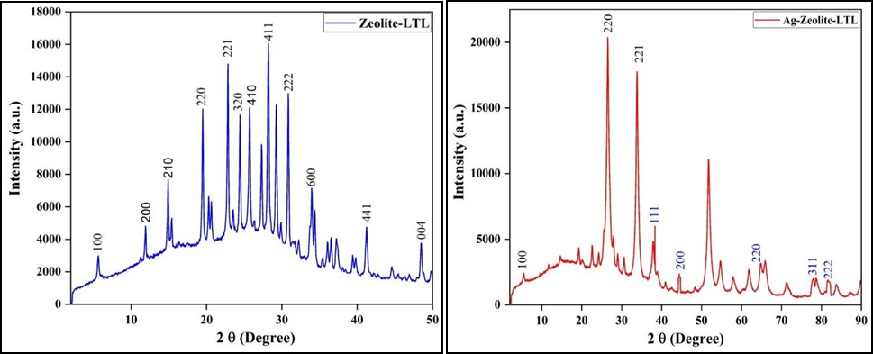
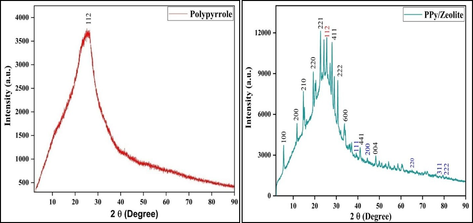
Figure 3. XRD Spectra of (a) Zeolite LTL, b) Ag-Zeolite-LTL, (c) PPy, (d) Composite
The average crystallite size of PPy/Zeolite-LTL nanocomposite was estimated by using Scherer’s equation:
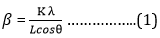
Where β is crystallite size in nm, K-crystal shape factor (have value 0.9 or 1.0), λ- wavelength Cu Kα (1.542 Å), L-full width at half maxima (FWHM) and θ- is the Bragg’s angle. The crystalline size of ion exchange Zeolite and composite are 35 nm and 33 nm respectively.
FT-IR Analysis
Fourier transforms infrared spectroscopy (FTIR) was used to identify the adsorption site and structure of the Zeolite samples. Figure 4 (a, b, c and d) shows the FTIR spectra of synthesized Zeolite and modified Zeolite. The FTIR graph shows the absorption band at around 461 cm-1 and 613 cm-1. The symmetric stretching bands were observed in 726 cm-1 and 776 cm-1. The asymmetric stretch vibration bands were observed at 1027 cm-1. Water binding molecules and OH stretching bands were found around 1643 cm-1 and 3639 cm-1 respectively [27,28]. The absorption peaks in Zeolite composite were obtained at (600, 666, 713, 853, 965, 1025, 1160, 1296, 1450, 1543, 1102, 2342, and 2659) cm-1 which corresponding to the C-H bonding, the quinoid ring of vibration mode, C-N stretching of vibration, benzenoid ring stretching, the N-Quinoid ring stretching, N-H stretching vibrations respectively. All these peaks show the presence of Polypyrrole in the Zeolite composite [29].
SEM and Energy Dispersive X-ray (EDAX) Analysis
The morphology of the synthesized parent Zeolite and their composite-related images were more clearly observed by SEM.
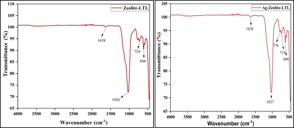
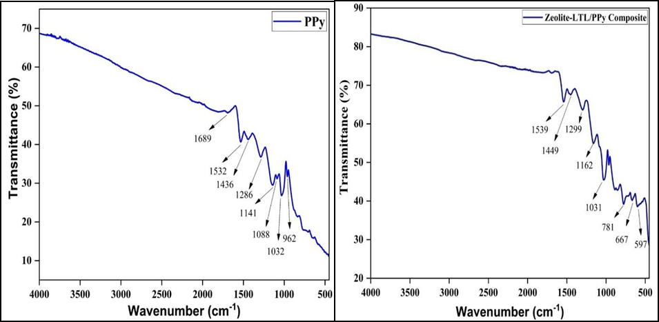
Figure 4. FTIR Spectra of (a) Zeolite LTL, (b) Ag-Zeolite-LTL, (c) PPy, (d) Composite.
The SEM images of synthesized material are shown in Figure 5 (a, b, c and d). These images show a regular hexagonal rod structure having an average length of 77.64 nm and a diameter of 23.52 nm. Due to the high surface charge, agglomeration and aggregation of crystals are visible and integrated [30,31]. The representation of the grains is regular and the microstructure consists of many neatly arranged rod-shaped Particles (nano-tablet tube). Their composite shows a cauliflower shape. From the SEM images of Zeolite polypyrrole was encapsulating in the zeolite’s materials.
The chemical composition or Elemental analysis for K, Al, Si, Ag, C, Cl, N and O in the pure Zeolite, modified Zeolite, Polypyrrole and their composites were carried out using energy dispersive X-ray microanalysis. Samples for EDAX analysis were coated with thin gold foil in order to avoid charge influence. The corresponding electron dispersive spectra of these samples are shown in Figure 6 (a-d).
In the EDAX spectra, Zeolite-LTL sample was found to contain the elements like Potassium, Aluminium, Silicon and Oxygen; Modified Zeolite contain the elements like Potassium, Aluminium, Silicon, Oxygen and Silver; Polypyrrole
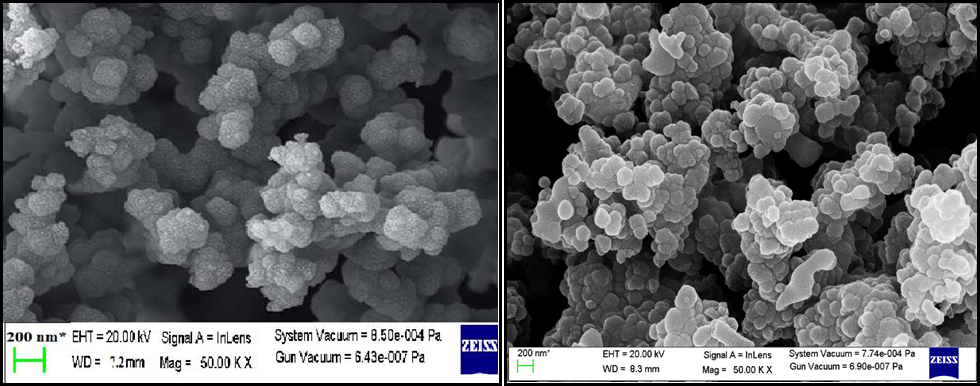
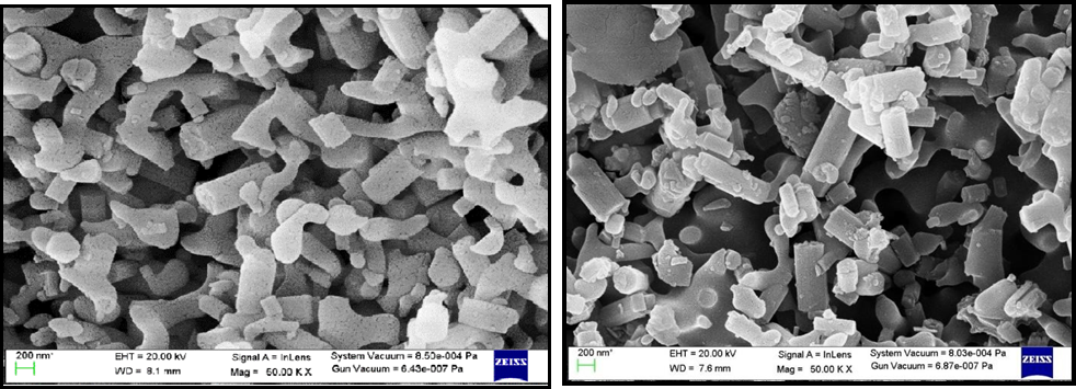
Figure 5. SEM Micrographs (a) Zeolite-LTL, (b) Ag-Zeolite-LTL, (c) PPy and (d) Composite.
particle contain the elements like Carbon, Oxygen, Sulfur and Nitrogen and these composites contain N, O, Al, Si, Cl, K, Ag and C elements indicating the successful of all the samples.
UV Vis Analysis
The optical properties of the Zeolite-Linde Type L and nano composite were determined by observing the optical absorption spectra. From the absorbance spectra, it is clearly seen that both the sample shows optical activity in the visible region.
The direct energy gaps (band gap) were determined from the relation for direct band gap semiconductors by using the following equation:
(