2020: Volume 2, Issue 1
Past Issues
 Abstract
  PDF
PDFReliability Design of Mechanical Systems Subjected to Repetitive Stresses
Seong-woo Woo1*, Dereje E. Woldemichael1, Samson M. Atnaw1, Muluneh Mekonnen Tulu1, Dennis L. O’Neal2
1Addis Ababa Science & Technology University, Ethiopia 2Dean of Engineering and Computer Science, Baylor University, Waco, TX 76798-7356
*Corresponding author: Seong-woo Woo, Addis Ababa Science & Technology University, Ethiopia, Tel: +251-90-047-6711; E-mail: [email protected]. Received: August 21, 2020 Published: November 27, 2020
ABSTRACT
To improve the lifetime of mechanical system, parametric Accelerated Life Testing (ALT) as new reliability methodology suggests to assess the design of mechanical systems subjected to repetitive stresses. It includes: (1) a parametric ALT plan based on product BX lifetime, (2) a load analysis for accelerated life time test, (3) a tailored sample of parametric ALTs with the design modifications, and (4) an evaluation of whether the final design(s) of the product achieves the target BX lifetime. We suggest a generalized life-stress failure model with a new effort concept, accelerated factor, and sample size equation with the acceleration factor. As a test case, based on field data and a tailored set of accelerated life tests, the redesign of hinge kit system (HKS) in a refrigerator was studied. To carry out parametric ALTs, using a force and moment balance analysis, the mechanical impact loads of HKS were calculated in closing the refrigerator door. At the first accelerated life testing (ALT), the HKS failure happened in the fracture of the kit housing, and oil damper leaked when the HKS broke. The failure modes and mechanisms found in the 1st ALT were similar to those of the failed samples obtained in the field. The missing design parameters of the HKS included the stress raisers such as corner rounding and rib of the housing hinge kit, the oil seal in the oil damper, and the material of the cover housing. In the second ALT, the fracturing occurred in the cover housing. The missing design parameter of the cover housing in the HKS was the plastics material. As a corrective action plan, we modified the cover housing from plastic to aluminum. After two rounds of parametric ALTs with corrective action plans, the lifetime of the redesigned HKS was guaranteed to be a B1 life of over10 years with a yearly failure rate of 0.1%.
KEYWORDS: Lifetime Design; Hinge Kit System; Fracture; Parametric Accelerated Life Testing; Missing Design Parameter
NOMENCLATURE
AF: Acceleration factor; BX: Durability index; C1: Housing design of HKS; C2: Oil damper sealing structure; C3: Cover housing material; F(t): Unreliability; F: Force, kN; F1: Impact force under accelerated stress conditions; F0: Impact force under normal conditions; h: Testing cycles (or cycles); h*: Non-dimensional testing cycles, h*=h/LB>1; KCP: Key Control Parameter; KNP: Key Noise Parameter; LB: Target BX life and x = 0.01X, on the condition that x£ 0.2; M: Moment around the hinge kit system, kN m; M1: Moment under accelerated stress conditions, kN m; M0: Moment under normal conditions, kN m; MA: Moment due to the accelerated weight, kN m; Mdoor: Moment due to the door weight, kN m; n: Number of test samples; N1: Consumer door open/close force, kN; r: Failed numbers; S: Stress; T: Friction torque, kN m; ti: Test time for each sample, h; TF: Time to failure, h; x: Required target x = 0.01·X; on condition that x£ 0.2; WA: Accelerator weight, kg; Wdoor: Accelerator weight; kg: Greek symbols; h: Characteristic life; λ: Cumulative damage exponent in Palmgren-Miner’s rule Superscripts; b: Shape parameter in a Weibull distribution; nStress dependence; 
SUBSCRIPTS : 0 : Normal stress conditions ; 1 : Accelerated stress conditions.
INTRODUCTION
The mechanical products such as automobile, airplane, and refrigerator [1] manage power, which produce mechanical advantages by adapting product mechanisms. Most mechanical products are composed of multi-module structures. If the modules are assembled, mechanical product can work properly and perform their own intended functions. For example, to store food fresh, refrigerator is designed to provide cold air from the evaporator to the freezer (or refrigerator) compartment. It can consist of several different modules – cabinet, door, internal fixture (shelves and drawers), controls and instruments, generating parts (motor or compressor), heat exchanger, water supply device, and other miscellaneous parts. Total components have approximately 2,000 pieces.
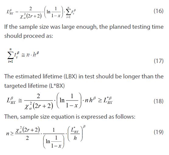
The reliability of mechanical product could be explained as the product of lifetime, LB, and failure rate l. That is, the total failure rate of an automobile over its lifetime is the sum of the failure rate of each module. Suppose that there were no initial failures in a product, we know that the product lifetime is determined by newly problematic designed module #3 such as HKS that will be discussed as case-study. The refrigerator lifetime is expected to beat a B20 life 10 years. Because refrigerator consists of 20 units if each unit has 100 components, lifetime of each unit is strictly targeted to be B1 life 10 years. We can carry out parametric ALT for newly designed mechanical system to search out the design problems (Figure 1&2).
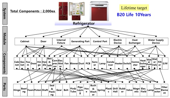
Figure 1: Breakdown of refrigerator with multi-modules.
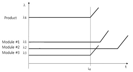
Figure 2: Product lifetime LB and failure rate λs with multi-modules.
To avoid the failure of mechanical system in the field, it must be designed to robustly endure the operating conditions imposed by the consumers who purchase and use. Any design faults therefore should be identified and modified through statistical methodology [2] or reliability testing [3] before a product is launched. However, they requires huge computations for optimum solution but have no results because of not figuring out failure mechanics. That is, if there are design faults that causes an inadequacy of strength (or stiffness) when a product is subjected to repetitive loads, the product will collapse before its expected lifetime due to fatigue failure.
To search out the failure, its modes and effects of a product, the representative methodologies are stress–strength interference analysis [4], failure modes, effects, and criticality analysis (FMEA/FMECA) [5], and fault tree analysis (FTA) [6]. In the product design process, these typical analyses are carried out by a company's experts for documentation. Because the critical design parameters of a new product is frequently missed in reviewing them, the product would experience field failures and then have to be recalled. Especially, stress/strength interference model figures out why mechanical products fail in the gradual wearout process. It also defines product failure as the probability that stress exceeds strength. However, because product failure occurs suddenly from the weakest parts of a product, it requires the complementary design concepts such as fracture mechanics [7] and life-stress model [8].
To implement the optimal design of a mechanical structures, engineer has studied on traditional design approaches such as strength of materials [9]. On the other hand, a recent fracture mechanics study proposed the critical factors be flaw size and fracture toughness instead of strength as a relevant material property. As quantum mechanics advances in electronic technology, engineers have recognized product failures from micro-void coalescence (MVC), which is observed in the majority of metallic alloys or some engineering plastics. To figure out the failure phenomena of mechanical product, a better life-stress model should be combined with the traditional design approaches and applicable to electronic parts and a small crack or pre-existing defect that is clearly unfeasible to model using FEM [10].
To obtain the solution of product failures in the field, there is another engineering approach includes the finite element method (FEM) [11]. Many engineers think infrequent product failures can be assessed by: (1) mathematical modeling using Newtonian or Lagrangian methods, (2) after obtaining the time response of the system for dynamic loads, finding the product stress/strain from it, (3) utilizing the rain-flow counting method for von Mises stress [12], and (4) estimating system damage using the Palmgren–Miner's rule [13]. However, using an analytical methodology that can produce a closed-form, exact solutions would involve invoking many assumptions that are not capable of identifying multi-module product failures due to micro-void, contacts, design flaws, etc. when subjected to loads.
This study presents a parametric ALT as reliability methodology that can be applied to mechanical systems [14]. It includes: (1) a parametric ALT plan based on product BX lifetime, (2) a load analysis for accelerated lifetime test, (3) a tailored sample of parametric ALTs with the design modifications, and (4) an evaluation of whether the final design(s) of the product achieves the target BX lifetime. As a test case, we will discuss as following: the redesign of hinge kit system (HKS) in a refrigerator.
ACCELERATED LIFE TESTING FOR MECHANICAL SYSTEM
II-1 Setting an overall testing plan for parametric ALT
Reliability can be defined as the ability of a system or module to function under stated conditions for a specified period of time. Product reliability can be illustrated by a diagram called a “bathtub curve” that consists of three parts. First, there is a decreasing failure rate in the early life of the product (β<1). Then, there is a constant failure rate (β=1). Finally, there is an increasing failure rate toward the end of the product's life (β>1). If a product follows the bathtub curve, it may have difficulties succeeding in the marketplace because of the higher failure rates and shortened lifetime due to design faults. Companies can positively improve the design of a product by setting reliability goals for new products to (1) reduce early failures, (2) decrease random failures during the product operating time, and (3) increase product lifetime. As the reliability of a mechanical product improves, the failure rate of the product in the field declines and its lifetime extends. For such a situation, the traditional bathtub curve can be transformed to a straight line with the shape parameter β (Figure 3).
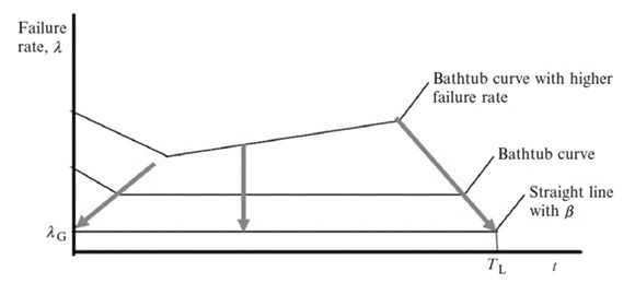
Figure 3: Bathtub curve and straight line with slope β toward the end of the life of the product.
Because the straight line with a low failure rate follows an exponential distribution, the cumulative failure function of a mechanical product might be quantified from the product lifetime LBX and failure rate λ as follows:
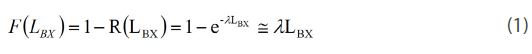
This equation is applicable to ≤ 20% of cumulative failures, F(×) [15]. After targeting the product lifetime LBX, engineer should identify any design faults and modify them through parametric ALT (Figure 4 and Table 1).
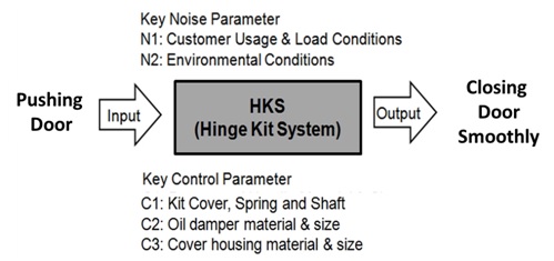
Figure 4: Parameter diagram of mechanical system – HKS (example).
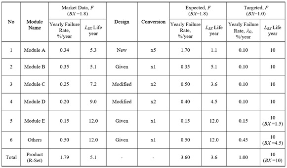
Table 1: Setup Overall parametric ALT plan for a mechanical system – refrigerator (example).
In targeting the BX lifetime of a mechanical system for parametric ALT, there are (1) a new module, (2) a modified module, and (3) a similar module where there is no modification to the prior design on the basis of market data. A HKS that will be case-studied can be regarded as a new module added because customers wanted the door to close gently. Like module A listed in Table 1, HKS from the field had yearly failure rates of 0.34% per year and a lifetime of B1.8 life 5.3 years. To respond to customer claims, a new lifetime for the compressor was set to B1 life 10 years.
II-2Failure mechanics and accelerated testing for design
Mechanical systems transfer power from one place to another through its mechanisms. A HKS as one of mechanical system gently closes the refrigerator door by adapting mechanism. In the process HKS are subjected to repetitive stress due to loads. If there is a void (design fault) in the structure that causes an inadequacy strength (or stiffness) when the loads are applied, HKS may abruptly fail during its expected lifetime. After identifying the product failure by experiments such as parametric ALT, an engineer can optimally design the HKS shape and select a proper material. The HKS sustains repetitive loads in its lifetime so that it can achieve the targeted reliability (Figure 5).
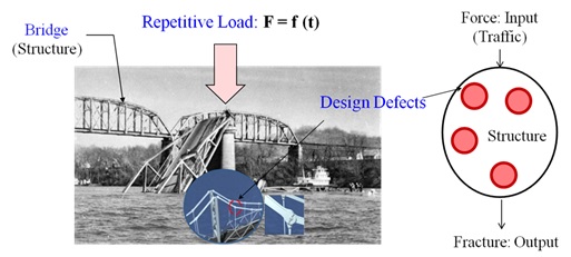
Figure 5: Failure mechanics on the structure created by (random) repetitive load and design defects.
The most important issue for a reliability test is how early the potential failure mode can be found. To do this, it is necessary to formulate a failure model and determine the related coefficients. First of all, we can configure the life-stress (LS) model, which includes stresses and reaction parameters. This equation can explain various failures such as fatigue in the mechanical structure. Fatigue failure arises, not due to theoretical stresses in a perfect part, but rather due to the presence of a small crack or pre-existing defect on the surface of a component that become plastic by the implied stress. To better understand it, engineer recognizes how small crack or pre-exited material defects in material generate. That is, because system failure starts from the presence of a material defects formed on a microscopic when repeatedly subjected to a variable tensile and compression load, we might define the life-stress model from such a standpoint. For example, we can figure out the following processes utilized for solid-state diffusion of impurities in silicon that is popularly used as semi-conduct material: 1) electro-migration-induced voiding; 2) build-up of chloride ions; and 3) trapping of electrons or holes.
When electric magneto-motive force, x, is applied, we know that the impurities such as void in material formed by electronic movement is easily migrated because the barrier of junction energy is lowered and distorted/phase-shifted. For solid-state diffusion of impurities in silicon, the junction equation J might beexpressed as [16,17] (Figure 6):
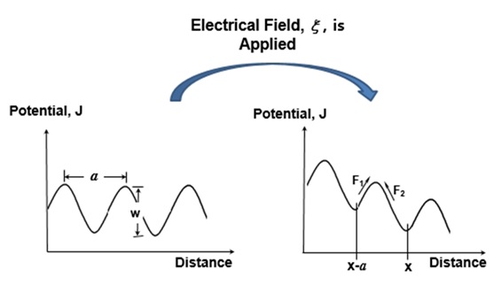
Figure 6: Potential change in material such as silicon after electrical field (or stress) is applied.
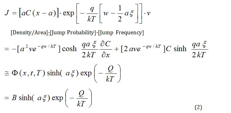
where B is constant, a is the distance between (silicon) atoms, x is the applied field, k is Boltzmann’s constant, Q is energy, and T is temperature.
On the other hand, a reaction process that is dependent on speed might be expressed as:
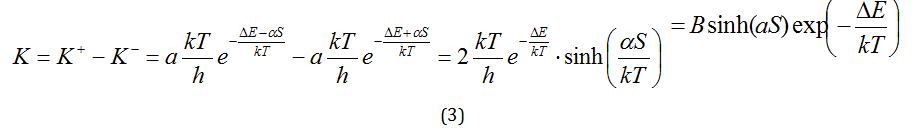
So the reaction rate, K, from Equations (2) and (3) can be summarized as:
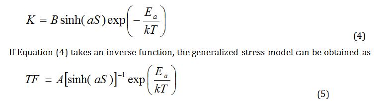
The hyperbolic sine stress term increases the stress as follows: (1) initially (S)-1 in low stress effect, (2) (S)-n in medium stress effect, and (3) (eas)-1 in high stress effect. Ductile metals in the stress-strain curve go through the specification limits, operating limit, yield point, and ultimate stress point into fracture. Because accelerated testing will be conducted in the medium range between specification limits and the operating limits, Equation (5) is redefined as follows (Figure 7):
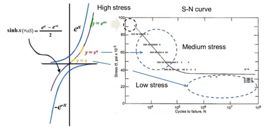
Figure 7: Hyperbolic sine stress term versus S-N curve.
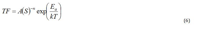
Because the stress of mechanical system is difficult to quantify in testing, we need to modify Equation (6). When the power is defined as the product of effort and flows, stresses may come from effort in a multi-port system [18].
So Equation (6) can be replaced as the more general term effort (e):
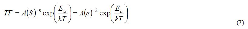
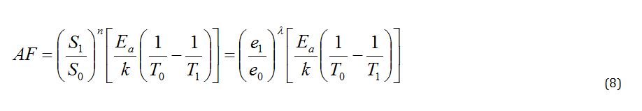
Design defects in products can be found by applying larger effort under the accelerated environment conditions. From the time-to-failure in Equation (7), an acceleration factor (AF) can be defined as the ratio between the proper accelerated condition levels and typical condition levels. AF can be modified to include the effort concepts:
II-3Parametric accelerated life testing of mechanical systems
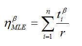
To derive the sample size equation and carry out a parametric ALT, the characteristic life hneeded to be estimated from the Weibull distribution. First, the characteristic life hMLE from the Maximum Likelihood Estimation (MLE) was derived as:
 (9)
(9)
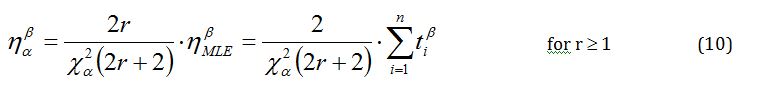
If the confidence level was 100(1 - a) and the number of failures was r³ 1, the characteristic life, ha, could be estimated from equation (9),
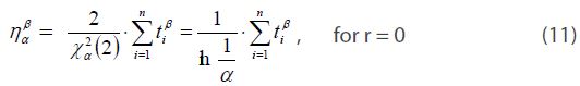
If there was no failures, the p-value was alfa and In (1/alfa) was mathematically equivalent to the Chi-square value,  .
.
The characteristic life nalfa, would be expressed as:
Because equation (10) was established for all cases r³ 0, it can be redefined as:
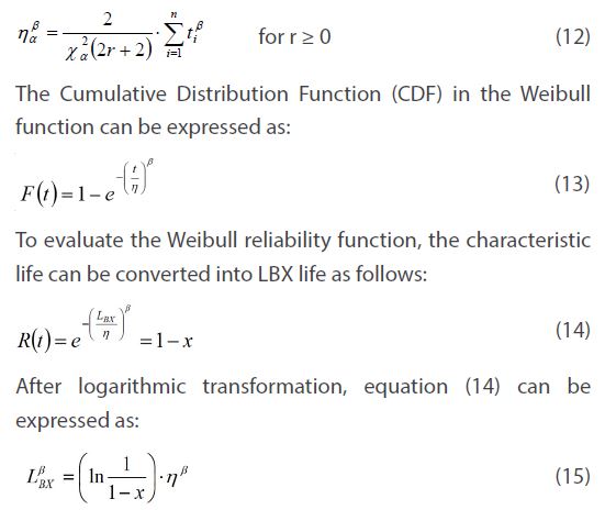
If the estimated characteristic life of p-value a, ha , in equation (12), was substituted into equation (11), we obtain the BX life equation:
The lifetime target of the new HKS was guaranteed to be B1 life 10 years. Based on the expected customer usage conditions, the normal range of operating conditions and cycles of the product (or parts) were investigated. Under the worst case, the number of required test cycles could be obtained from equation (20) for given sample pieces. ALT equipment can then be conducted on the basis of load analysis. In parametric ALTs, the missing parameters of HKS in the design phase could be identified to achieve the lifetime target – B1 life 10 years.
III. Case study: reliability design of the hinge kit system (HKS)
When a consumer uses the door in commercially produced refrigerator, they usually want the door to close gently. For this (intended) function, the hinge kit system needs to be designed to handle the operating conditions subjected to it by the consumers who purchase and use the refrigerator. The primary components in a HKS consists of a kit cover, shaft, spring, and oil damper, etc (Figure 8).
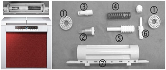
Figure 8: Commercial Refrigerator and its HKS. (a) Refrigerator and HKS ; (b): Mechanical parts of HKS: kit cover ①, oil damper ②, fixed cam ③, spring ④,cam ⑤, shaft ⑥, and HKS housing ⑦.
The functional loss of the original HKS had been reported often by owners of the refrigerator. The data of the failed products in the field were important for understanding and determining the usage patterns of consumers and helping to pinpoint design changes that needed to be implemented in the product. Based on field data, failure analysis was required to find out the root cause(s)of the defective HKS and what component(s) in the HKS needed to be redesigned to improve reliability.
In the field, the HKS parts of refrigerator were failing due to cracking and fracturing underunknown consumer usage conditions. When comprehensive data from the field were reviewed, the damaged products might have had structural designflaws, including sharp corner angles and not enough enforced ribs resulting in high stress concentrations. These design flaws, combined with the repetitive impact loads on the HKS, could cause a crack to occur, and thus cause failure (Figure 9).
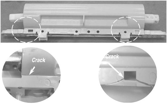
Figure 9: Example of damaged products returned from the field.
The closing function of the HKS included several mechanical structural parts. Depending on the consumer usage conditions, the HKS was often subjected to repetitive mechanical impact loads when the consumer closed the door. Door closing involved the simple mechanical processes: (1) the consumer opened the door to take out or storefood, and (2) they then closed the door by force.
In the process, the HKSs were subjected to different loads during the opening and closing of the refrigerator door. To find out the required acceleration factor, it was important to understand the forces on the HKS during closing. Because the HKS was a relatively simple mechanical structure, the forces impacting the HKS could be modeled with a simple force-moment equation. As the consumer opened or closed the refrigerator door, the stress due to the weight momentum of the door was concentrated on the HKS (Figure 10).
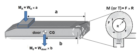
Figure 10: Design concept of HKS.
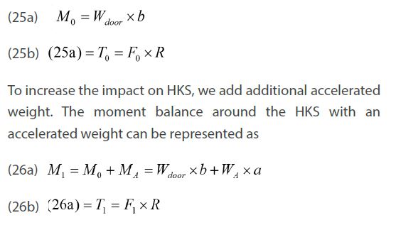
Because the time to failure depends on impact force due to moment, we can carry out the accelerated life testing as controlling the impact. Under the same working conditions, the life-stress model (LS model) in equation (7) could be modified as
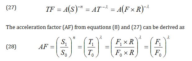
The operating conditions for the HKS in a refrigerator were approximately 0–43°C with a relative humidity ranging from 0% to 95%, and 0.2–0.24g’s of acceleration. The opening and closing of the door occurred an estimated average of 3 to 10 times per day. With a life cycle design point for10 years, the life of HKS incurred about 36,500 usage cycles for the worst case scenario. For this worst case, the impact force around the HKS was 1.10 kN which was the expected maximum force applied by the typical consumer. For the ALT with an accelerated weight, the impact force on the HKS was 2.76 kN. Using a stress dependence of 2.0, AF was found to be approximately 6.3 in equation (28).
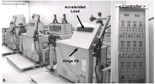
Figure 11: Equipment used in the accelerated life testing and the controller. (a) ALT Equipment ; (b) Controller.
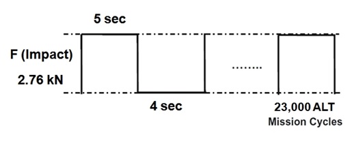
Figure 12: Duty cycles of the repetitive impact load F on the HKS.
For the lifetime target – B1 life 10 years, the test cycles forsample six pieces calculated in Eq. (20) were 23,000 cycles if the shape parameter was supposed to be 2.0. This parametric ALT was designed to ensure a B1 life of 10 years with about a 60% level of confidence that it would fail less than once during 23,000 cycles. Figure 11 shows the experimental setup of the ALT with labeled equipment for the robust design of HKS. As seen in figure 12, repetitive stress can be expressed as the duty effect due to the on/off cycles and HKS shortens part life.
The control panel was used to operate the testing equipment. It controlled the number of tests, the testing time, and the starting or stopping of the equipment. When the start button on the controller panel was pressed, the simple hand-shaped arms couldhold and lift the refrigerator door. As the door was closing, it could apply to the HKS the maximum mechanical impact force required to reproduce the accelerated load (2.76 kN).
Results and discussions
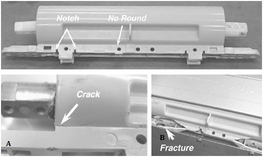
Figure 13: Failed products in field and crack after 1stALT. (a) Failed products in field, (b) crack after 1stALT.
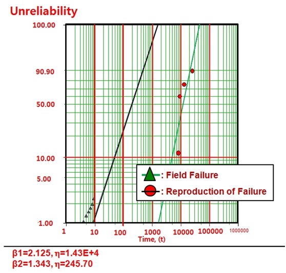
Figure 14: Field data and 1stALT on Weibull chart.
Figure 13 shows a photograph comparing the failed product from the field and that from the 1staccelerated life testing, respectively. In the 1st ALT, the housing of the HKS fractured at 3,000 cycles and 15,000 cycles. As shown in the picture, the tests confirmed that the HKS housing hada weak structure nearthe notch because there were no rounded edges. The defective shape of the 1stALT was very similar to that of the ones from the field. Figure 14 represented the graphical analysis of the ALT results and field data on a Weibull plot. That is, from the similar two slopes, we recognized the failure patterns shown in 1st ALT and field were close under repetitive stress. As the shape parameter was initially estimated at 2.0, the shape parameter was confirmed to be 2.1 from the Weibull plot of the first ALT.
Based on test results and Weibull plot, parametric ALT was valid because it pinpointed the design weaknesses that were responsible for the failures in the field. As supported by two findings, these methodologies were valid in pinpointing the problematic designs responsible for failures in the field, which determined the lifetime.When breaking down the HKS, we found that the oil damper leaked into the hinge kit assembly at 15,000 cycles (Figure 15). Because of the repetitive impacts of the opening and closing of the HKS in combination with its structural design flaws, the housing of the HKS fractured and the oil damper leaked. Based on finite element analysis, the concentrated stresses of the housing HKS was about 21.2 MPa. The stress raisers in highstress areas resulted from the design flaws like sharp corners/angles, housing notches, and poorly enforced ribs.
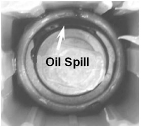
Figure 15: Spilled oil damper in 1st ALT.
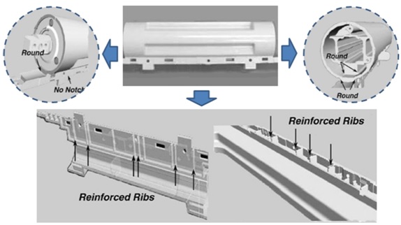
Figure 16: Redesigned HKS housing structure (missing parameter – C1).
The corrective action plans for the weak HKS housing were to make fillets, add the enforced ribs, and round the notching on the housing of HKS (Figure 16). Applying the new design parameters, the stress concentrations in the housing of HKS decreased from 20.0 MPa to 10.5 MPa when we analyzed in finite element method. Therefore, a corrective action plan had to be prepared at the design stage before production.
When the leaking oil damper was examined, the sealing structure in the oil damper had a 0.5 mm gap in the O-ring/Teflon/O-ring assembly. Due to the impact of the door closings, we knew that this sealing structure with the gap leaked easily for first ALT. With the corrective action plan, the sealing structure of the redesigned oil damper hadbeen changed to no gap with the Teflon/O-ring/Teflon (Figure 17).
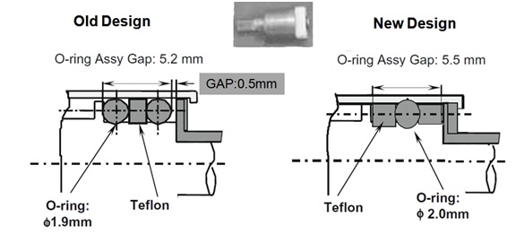
Figure 17: Redesigned oil damper (missing parameter – C2).
A) 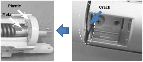
B) 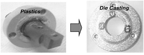
Figure 18: A) Structure of problematic products at 2ndALT. B) Redesigned cover housing (missing parameter – C3).
The newly designed samples were to have more than the lifetime target – B1life10 years. The confirmed values of AF and β in figure 14 were 6.3 and 2.1, respectively. The recalculated test cycles in equation (24) were 24,000 for sample six pieces. To obtain the design flaws of the HKS, 2ndALTs were performed. In the second ALTs the fracture of hinge kit cover occurred in the cover housing of HKS at 8,000, 9,000, and14,000 cycles (Figure 18). The root cause of these fractures came from striking the cover housing (plastic) by the support of oil damper (aluminum). As a corrective action plan, the material of cover housing changed from the plastics to the Al die-casting. Finally, the redesigned HKS could withstand the high impact force during closure of the door.
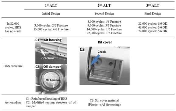
Table 2: Results of ALT.
To withst and the HKS design problems due to the repetitive impact loads, the HKS system was redesigned as follows: (1) reinforcing the housing design of HKS, C1; (2) changing the sealing structure in the oil damper, C2; (3) changing cover housing material,C3, from plasticsto the Al die-casting. With these design changes, the refrigerator could also be opened and closed more comfortably over its product lifetime. Table 2 shows the summary of the results of the ALTs. With these modified parameters, the Refrigerator door could be gently closed for a longer period without failure. Over the course of three ALTs, the B1 life of the samples was guaranteed to be 10.0 years.
CONCLUSIONS
To improve the lifetime of a newly designed mechanical system such as HKS, we have suggested a parametric ALT as reliability methodology that includes: 1) a parametric ALT plan, 2) a load analysis, 3) a tailored series of parametric ALTs with action plans, and 4) an evaluation of the final design requirements of the HKS to ensure they were satisfied. A hinge kit system in the refrigerator was used as a case study.
- Based on the products that failed both in the field and in 1stALT, the failure of HKS occurred in the fracture of the kit housing and oil damper leaking. The missing design parameters of the failed HKS in the design phase were the oil sealing structure and the housing of the hinge kit that was caused from the concentrated stress due to improper fillets, ribs, and notching. The corrective action plans were the modifications of the housing hinge kit and the redesigned sealing structure of oil damper.
- Based on the 2ndALT, the fracturing of HKS occurred in the cover housing. The missing design parameter of the failed HKS was the material of cover housing. As a corrective action plans, the cover housing from plastic to aluminum was modified. After a sequence of ALT testing, HKS with the proper values for the design parameters were determined to meet the lifetime target –B1 life 10 years.
- As new reliability design methodologies, we knew that inspection of the failed product, load analysis, and three rounds of ALT was greatly improved for the newly designed HKS in Refrigerator. This new reliability methodology might be applicable to mechanical systems such as airplane, automobiles, refrigerators, construction equipment, washing machines, and vacuum cleaners. To use this new reliability methodology, engineers should understand why products fail. That is, if there are design faults in product that causes inadequacy of strength (or stiffness) when subjected to repetitive loads, the mechanical product will collapse in its lifetime.
REFERENCES
- Nag PK. Engineering thermodynamics, Tata McGraw - Hill Education Pvt. Ltd., New Delhi, 2005.
- Rosa JL, Robin A, Silva MB, Baldan CA, Peres MP. (2009). Electrodeposition of copper on titanium wires: Taguchi experimental design approach. Journal of Materials Processing Technology. 209(3):1181–1188.
- Montgomery D. Design and analysis of experiments, 8th edition, John Wiley, Hoboken (NJ). 2013.
- Tersmette T. 2013. Mechanical stress/strength interference theory, Quanterion.
- Rausand M, Høyland A. System Reliability Theory: Models, Statistical Methods, and Applications, Wiley Series in probability and statistics, 2nd Edition, 2004, p. 88
- Center for Chemical Process Safety, Guidelines for Hazard evaluation procedures, 3rd edition, Wiley, 2010.
- Ewalds HL, Wanhill RJH, Fracture Mechanics. London: Edward Arnold, Delft, Netherlands: Delftse Uitgevers Maatschappij, 1984.
- McPherson J. Accelerated testing, Electronic materials handbook Volume 1: Packaging. ASM International Publishing, Materials Park (OH), 1989, pp. 887–894.
- Beer P, Johnston Jr. Mechanics for Engineers, 5th Ed., McGraw-Hill, New York, 2008.
- McPherson J. Reliability physics and engineering: time-to-failure modeling, Springer. New York. 2010.
- Logan DL. A First Course in the Finite Element Method, Cengage Learning, Inc., 2011.
- Sunder R, Seetharam SA, Bhaskaran TA. 1984. Cycle counting for fatigue crack growth analysis, International Journal of Fatigue. 6(3):147–156.
- Palmgren AG. 1924. Die Lebensdauer von Kugellagern, Z Ver Dtsch Ing. 68(14):339–341.
- Woo S, Pecht, O’Neal D. (2020). Reliability design and case study of the domestic compressor subjected to repetitive internal stresses. Reliability Engineering & System Safety. 193:106604.
- Kreyszig E. Advanced Engineering Mathematics, 9th edition, John Wiley and Son, New Jersey, 2006;p. 683.
- Grove A. Physics and technology of semiconductor device, 1st edition, Wiley International Edition.p. 37.
- ASM International, Electronic materials handbook Volume1: packaging, 1989;p. 888.
- Karnopp DC, Margolis DL, Rosenberg RC. System dynamics: modeling, simulation, and control of mechatronic systems, 5th edition, John Wiley & Sons, New York, 2000.
- Woo S, Pecht M. (2008). Failure analysis and redesign of a helix upper dispenser. Eng Fail Anal. 15(4):642–653.
- Woo S, O'Neal D, Pecht M. (2009). Design of a hinge kit system in a Kimchi refrigerator receiving repetitive stresses. Eng Fail Anal. 16(5):1655–1665.
- Woo S, O'Neal D, Pecht M. (2010). Failure analysis and redesign of the evaporator tubing in a Kimchi refrigerator. Eng Fail Anal. 17(2):369–379.
Copyright: Woo S, et al. ©2020. This is an open-access article distributed under the terms of the Creative Commons Attribution License, which permits unrestricted use, distribution, and reproduction in any medium, provided the original author and source are credited.
Citation: Woo S, et al. (2020). Reliability Design of Mechanical Systems Subjected to Repetitive Stresses. Material Sci. 2(1):07.